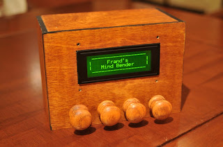
The objective is to get the display to read 'one true beautiful poem' by manipulating the knobs. Each knob can be pushed, pulled, twisted left, or twisted right. The knobs spring back into position after each operation, so it isn't like once a knob is pushed in it needs to be pulled back out before it can be pushed again.
A character named Frand (Jay Scott) created this puzzle within the MOO many years ago, so all credit for the idea goes to him. It is a tricky logic puzzle that will require several hours to solve and a systematic approach. I really enjoyed solving this puzzle when I originally found it on LambdaMOO because it had several distinct stages to the solving process, similar to the Patience Puzzle: first you need to understand the rules that govern the puzzle, then you use those rules to formulate a solution.
I had always thought it would be interesting to build a physical replica of this puzzle, but unfortunately I had no knowledge of electronics or microcontrollers. I did a bit of research and found out about something called a Basic Stamp, which is a microcontroller (little electronic brain for you non-techie folks) that you can program using a fairly simple programming language. The starter kit was about $100, but I am a fairly cheap bastard: I was worried that it might not work and I would be out $100 that could have been spent on puzzles.
One day, I was visiting a friend, Greg Charvat, who is a brilliant electrical engineering PHD who works at MIT. He was showing me around his shop and I noticed he had a Basic Stamp development board lying among the clutter. I told him I was actually thinking of buying one, and asked what he thought of it. He said he actually got it for free and wasn't planning on using it, so I could have it!
 Well now I had no excuse: I had my microcontroller and a development kit, now all I had to do was learn how to use them! Fortunately, there is plenty of material available for free online that walks you through the basics of learning to program a Basic Stamp. Greg also gave me some resistors and LEDs, so I practiced wiring and programming some simple projects that flashed LEDs and whatnot.
The next big hurdle was to find a display. Most displays are fairly small, but I needed one that could show a message that was potentially 44 characters long. This is far too long to show on a typical display without scrolling, so I needed to find one that would show multiple lines. In fact, since the the words that can be produced can be up to 13 characters long, I determined that I needed a display that would display four lines.
This tied into my next problem: I needed 16 inputs to control the puzzle, since there are four knobs and each one has four operations (push, pull, twist left, and twist right), but the Basic Stamp has exactly 16 dual funcion inputs/output pins! This left me with no way to output data to my display.
Fortunately, I discovered that there was a way to configure 16 switches that only requires 8 inputs: you can wire them in a matrix configuration where four of the i/o pins are the columns and four of the i/o pins are the rows (see 2x2 example on right). The 16 switches are laid out (logically) in a 4x4 grid so that when you press a switch it connects one row to one column, completing the circut. By checking regularly for this connection, you can determine exactly which switch has been pressed. It is tough to explain, so if you are confused (and prefer not to be) check out that link above because it explains it with diagrams.
Eventually I found the display of my dreams: a Matrix Orbital LK204-25-IY. It had a nice bright backlit screen, was compatible with my microcontroller, and, best of all, it was able to convert i/o from switches arranged in this matrix configuration into simple numbers that it could pass back to my microcontroller! That meant that I didn't need to worry about programming the logic that would repeatedly scan the switches to see if any were pressed. It did cost $70, but it was definitely worth it for all the features this thing has. Also, at this point I was fairly convinced that I was going to finish this project, so I was willing to suck it up and buy the display.
Stay tuned for the 2nd half of this entry tomorrow! I ran out of time tonight.


No comments:
Post a Comment
Please don't post spoilers! Thanks for commenting!